ARMv8-A 64-bit, 8-core, big.LITTLE 4xCortex-A76, 4xCortex-A55 and separate NEON co-processors
CPU Frequency
A76 : 2.4GHz, A55 : 1.8GHz
GPU
Arm Mali-G610/Built-in 3D GPU
NPU
Embedded NPU supports INT4/INT8/INT16/FP16, with up to 6Tops
Memory
LPDDR4 RAM
4GB/8GB/16GB/32GB (LPDDR4/4X)
eMMC 5.1 NAND Flash
32GB/64GB/256GB eMMC (optional) up to 400MB/s
SPI NOR Flash
QSPI Nor FLASH: 16MB/32MB
Internal Interfaces
M.2 M-Key
M.2 slot supporting 2280 NVMe SSD
M.2 E-Key
M.2 slot that supports Wi-Fi6/BT modules
External Interfaces
HDMI
2 x HDMI (OUT), 1 x HDMI(IN)
Ethernet
2 x PCIe 2.5G Ethernet ports (RTL8125BG)
USB Type-C
USB 3.0 Type-C(DP)
USB
2 x USB 3.0, 2 x USB 2.0
microSD
1
Others
PWM FAN
yes
RTC Battery
yes
Power
USB Type-C 5V/4A
FreeBSD 14.0 RELEASE does not support the RK3588 SoC, but thanks to Tianocore EDKII UEFI it is possible to use different operating systems, including FreeBSD. It was necessary to add a USB 2.0 driver for ACPI mode and fix the operation of the UART driver in this mode.
And now FreeBSD can be run on OrangePi 5 Plus from an SD card. The OS itself does not yet have a driver for an SD card and eMMC, but the system can be installed on a USB FLASH or NVMe SSD.
HDMI, USB 2.0, USB 3.0, NVMe, Ethernet will work.
You can try installing FreeBSD on OrangePi 5 Plus.
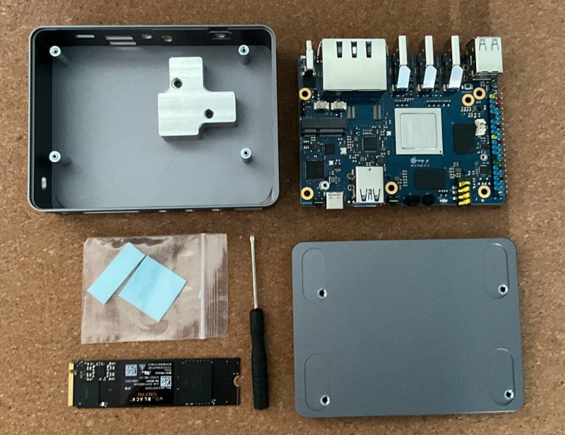
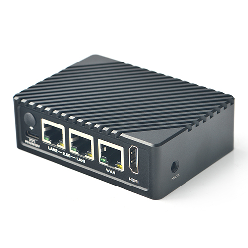
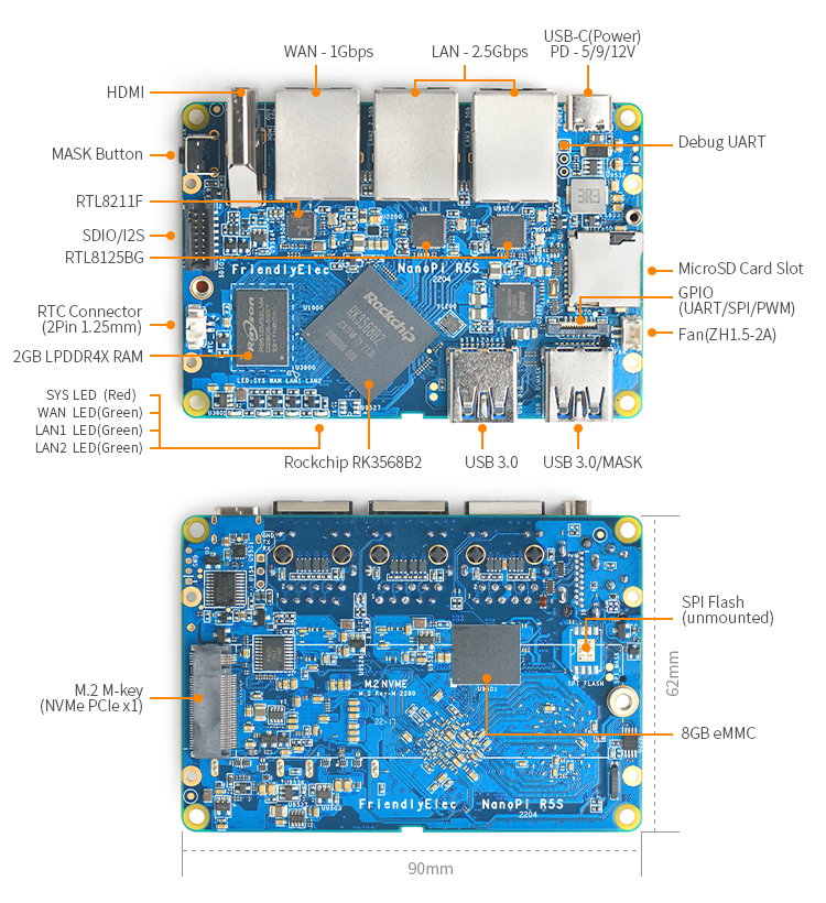
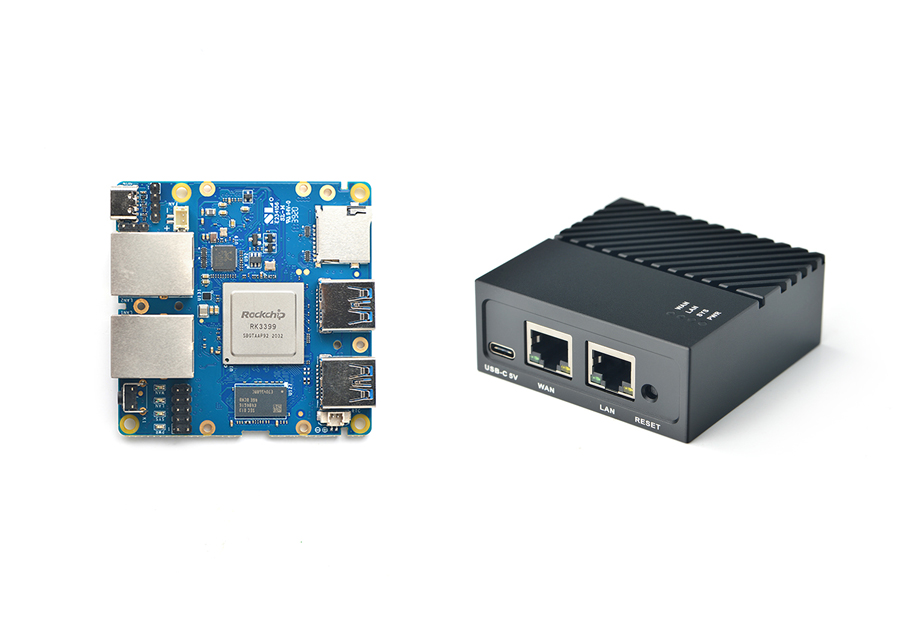
The NanoPi R5S (as “R5S“) is an open source platform with two 2.5Gb and one 1Gb Ethernet ports designed and developed by FriendlyElec for IoT applications.
The NanoPi R5S uses the RockChip RK3568B2 SoC. It has and 2G/4G RAM, eMMC, USB, HDMI and M.2 NVMe socket.
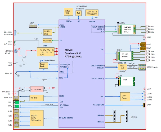
Globalscale Technologies has created a new open source quad core networking board designed to provide users with high-speed connectivity using the Wi-Fi, 5G, 1Gbit and 10Gbit Ethernet.
The Mochabin is designed for a variety of Firewall, Networking and NAS applications.
Mochabin is designed to support 4G and 5G applications via the M.2 interface. These can be used for cellular backhaul and communications to replace the ISP modem.
With the OpenWRT and Replica One software.
We are interested in installing FreeBSD/OPNsense/TrueNAS on this board.
МochaBin-5G SBC diagram.
Board Specifications
SoC Model
Marvell Armada 7040 quad-core Corex-A72 processor Product Breaf
SoC Architecture
ARMv8 64-bit
CPU Frequency
UP to 1.4GHz
Memory
RAM
4GB or 8GB DDR4 (soldered down)
eMMC flash
16GB
SPI NOR flash
4MB for bootloader
External Interfaces
LAN Port (10Gbe)
1x 10GbE SFP+, 1x 1GbE SFP (via 88E1512 PHY)
LAN Port (1Gbe)
4x Gigabit Ethernet RJ45 via Topaz 88E6141 switch
WAN Port (1Gbe)
1x Gigabit Ethernet RJ45 WAN port (via 88E1512 PHY) with PoE support, multiplexed with 1GbE SFP, so only one can be used at any time
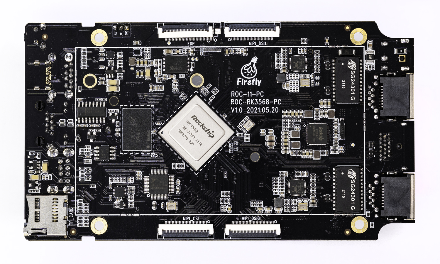
RK3568 quad-core 64-bit processor RK3568 quad-core 64-bit Cortex-A55 processor, with brand new ARM v8.2-A architecture, has frequency up to 2.0GHz — the efficiency is greatly improved. With 22nm lithography process, it features low power consumption and high performance.
8GB large RAM, all-data-link ECC Supporting up to 8GB RAM, with up to 32Bit width and frequency up to 1600MHz, it supports all-data-link ECC, making data safer and more reliable. The large RAM fits the needs of smoothly running apps with large amount of data and high speed requirements.
Integrated co-processors — GPU, VPU, NPU
It is integrated with dual-core GPU, high-performance VPU and high-efficiency NPU. The GPU supports OpenGL ES3.2/2.0/1.1, Vulkan1.1. The VPU can achieve 4K 60fps H.265/H.264/VP9 video decoding and 1080P 100fps H.265/ H.264 video encoding. The NPU supports one-click switching of mainstream frameworks like Caffe/TensorFlow.
4K HDR vision The new video engine VPU can easily decode H.265/HEVC/VP9 4K HDR videos, supports 3840×2160@60Hz ultra-HD output and HDR10 — optimizes the dynamic range and details of the image frame by frame, enhances the image quality and color performance, delivering clear and vibrant vision experience.
Dual Gigabit Ethernet ports The dual adaptive RJ45 Gigabit Ethernet ports, through which internal and external network data can be accessed and transmitted, improves the network transmission efficiency. Dual Gigabit Ethernet ports deliver better network scalability, and can be used in scenarios such as setting up family gigabit network, DIY gigabit router, soft router, OpenWrt.
Powerful wireless network communication WiFi 6 (802.11ax) wireless network communication is supported, with the maximum bandwidth reaches 160MHz and the highest speed reaches 9.6Gbps — the speed is greatly improved than WiFi 5. And, WiFi 6 delivers lower packet loss rate and retransmission rate, making the transmission more stable and secure.
Onboard M.2 and SATA3.0 interfaces The onboard M.2 PCIe3.0 and SATA3.0 interfaces can be connected with an M.2 NVMe SSD and a 2.5-inch SATA SSD/HDD respectively, owning the advantages of high-speed reading and writing and large capacity.
RS485 and RS232 interface extension The configured Control Port (RJ45) provides one RS485 and two RS232, through which you can connect to external devices with RS485/RS232 serial port to control more external devices flexibly and create more fun ways to play.
Excellent heat dissipation
Toothed aluminium alloy case in matte black under high-precision CNC machining and with good air flow design makes excellent heat dissipation, even without fans.
A variety of interfaces HDMI2.0, USB3.0, USB2.0 x 2, Control Port (RS485 x 1, RS232 x 2), Type-C (OTG), LAN x 2, TF CARD and other interfaces are provided.
Configured with Geek System
Station OS (Firefly Geek System) brings you living room playing experience. Just connect the TV or display at home to build a home entertainment center to enjoy movies and games with high-definition and big-screen viewing.
Various systems and boot ways supported It supports to upgrade to Android, Ubuntu, Linux+QT, Station OS and other systems, and supports to boot the system via TF card, U disk, EMMC, etc. Diverse supporting systems make entertainment, work, programming learning, creative development all easy.
Station application programs and forums Station application programs, including WeChat mini program, app and website, through which you can play videos, remotely control, remotely download and so on, enable you to play the geek computer anywhere anytime. Besides, forums with tremendous creative ideas and fun are waiting for you.
Firefly is a Team formed in 2014 by T-Chip Intelligent Technology Co., Ltd, focused on the research and development of open source intelligent hardware.
Firefly creates a platform full of scientific and technological creativity that makes product research and development efficient and simple so that creators can collect ideas and share them all together.
T-Chip Intelligent Technology Co., Ltd. specializes in providing hardware and software services and is committed to lowering the threshold for technological innovation to accelerate the integration of smart technology and life.
Firefly has released over 10 platforms and attracted over 200 000 community developers.
Firefly specializes in multi-platform application development as well as cloud service support, hardware schematics, and industrial design.
Firefly launches a series of products under the Station PC brand.
Station PC is the new Firefly series of single board computers that continues the open source functionality of Firefly and is more suitable for computer geeks.
In addition to its powerful configuration, this series is also supported by multiple operating systems, dedicated apps and player forums, allowing you to play and unleash your full creativity.
The solution is based on the Rochchip RK3399Pro processor.
This chip contains six processing cores – the Cortex-A72 duo clocked at up to 1.8 GHz and the Cortex-A53 quartet at up to 1.4 GHz.
The integrated Mali-T860 MP4 GPU controller with support for OpenGL ES 1.1–3.2, OpenVG1.1, OpenCL 1.2 and DX 11 is responsible for graphics processing.
It is important to note that the processor includes a specialized NPU designed to accelerate the execution of operations related to artificial intelligence.
The amount of LPDDR3 RAM ranges from 4 GB to 8 GB. Up to 64GB eMMC 5.1 flash drive and microSD card slot are provided. Additionally, up to 2TB M.2 NVMe SSD can be installed. The single board computer measures 100 × 100 mm. The product is equipped with a Gigabit Ethernet network controller. There are two USB 2.0 ports, a USB 3.0 OTG connector, an HDMI 2.0 interface and a standard 3.5mm audio jack.
The Rock Pi N10 starts at $99. It talks about compatibility with software platforms Debian 10, Ubuntu 18.04, Fedora 28 and Android 8.1.
I was able to build a FreeBSD 13.0-RELEASE boot image for this device, it allows you to install the operating system on an eMMC flash, NVMe SSD or USB HDD.
The NanoPi R4S (as “R4S“) is an open source platform with dual-Gbps Ethernet ports designed and developed by FriendlyElec for IoT applications.
The NanoPi R4S uses the RK3399 SoC. It has two Gbps Ethernet ports and 1G/4G RAM.
FriendlyElec ported anOpenWrt system for it. It works with Docker CE. It is a good platform for developing IoT applications, NAS applications, smart home gateways etc.
This is a great product that is ideal for use as an Internet gateway. I was able to create a custom build of the popular OPNsense firewall and FreeBSD13.1-RELEASE for this device. And it works great.
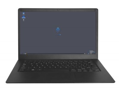
The Pinebook Pro is a Linux and *BSD ARM laptop from PINE64
It features an IPS 1080p 14″ LCD panel, a premium magnesium alloy shell, high capacity eMMC storage, a 10,000 mAh capacity battery, and the modularity that only an open source project can deliver.
Key features include: the RK3399 SOC; USB-C for data, video-out and power-in (3A 5V); privacy switches for the microphone, BT/WiFi module, and camera; and expandable storage via NVMe (PCIe 4x) with an optional adapter.
The Pinebook Pro is equipped with 4GB LPDDR4 system memory, high capacity eMMC flash storage, and 128Mb SPI boot Flash. The I/O includes: 1x micro SD card reader (bootable), 1x USB 2.0, 1x USB 3.0, 1x USB type C Host with DP 1.2 and power-in, PCIe 4x for an NVMe SSD drive (requires an optional adapter), and UART (via the headphone jack by setting an internal switch).
The keyboard and trackpad both use the USB 2.0 protocol. The LCD panel uses eDP MiPi display protocol.
Many different Operating Systems (OS) are freely available from the open source community and partner projects. These include various flavors of Linux (Ubuntu, Debian, Manjaro, etc.), NetBSD and OpenBSD.
Pine64 initially operated as Pine Microsystems Inc. (Fremont, California), founded by TL Lim, the inventor of the PopBox and Popcorn Hour series of media players sold under the Syabas and Cloud Media brands.
In 2015 Pine Microsystems offered its first product, the Pine A64, a single-board computer designed to compete with the popular Raspberry Pi in both power and price. The A64 was first funded through a Kickstartercrowdfunding drive in December 2015 which raised over $1.7 million. The Kickstarter project was overshadowed by delays and shipping problems. The original Kickstarter page referred to the Pine64 Inc. based in Delaware, but all devices for the Kickstarter campaign were manufactured and sold by Pine Microsystems Inc. based in Fremont, California.
In January 2020, Pine Microsystems Inc. was dissolved while Pine Store Limited was incorporated on December 5, 2019 in Hong Kong. As of late 2020, the standard form contract of pine64.com binds all orders to the laws of Malaysia, while the products are shipped from warehouses in Hong Kong and Shenzhen, PRC.


